What Is a Pressure Control Valve and How Does It Work?
A pressure control valve regulates fluid pressure by changing its flow path as operating conditions shift. In a hydraulic circuit, it may limit maximum pressure, reduce downstream pressure, or maintain back pressure. The exact function depends on its design and location. Some valves use a spring-loaded poppet; others rely on a spool, diaphragm, or pilot stage. Inside the body, a small movement can change the opening enough to affect pressure across an entire system. Greg McMillan, a process-control engineer and author, has emphasized: “The control valve is the most important final control element in a process control loop.” That idea applies here, though the right valve cannot compensate for every system problem.
Understanding how a pressure control valve works starts with force balance. Fluid pressure acts against a spring or another control force. When pressure rises or falls beyond the set point, the valve element moves, changing flow and helping restore the intended range. The response is not always immediate. Fluid temperature, contamination, incorrect sizing, and installation details can all affect performance. A gauge near the valve can reveal pressure changes that a distant instrument may miss. Small details matter.
This guide explains common valve types, internal components, operating principles, and practical selection factors. It also considers limitations: a pressure-control device does not automatically guarantee stable pressure under every load or flow condition. Real systems deserve testing, not assumptions. Pressure settings should follow equipment specifications and qualified engineering guidance.
What Is a Pressure Control Valve?
A pressure control valve is a hydraulic or pneumatic component that manages pressure in a system. It opens, closes, or changes flow when pressure reaches a set condition. Some valves reduce downstream pressure; others relieve excess pressure or maintain a minimum pressure in a circuit. The exact function depends on the valve design and its location. In practice, the term covers several different valve types. That can be confusing.
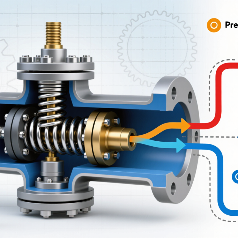
Inside the valve, a spring may oppose fluid pressure on a spool, poppet, or diaphragm. When the pressure force overcomes the spring setting, the moving part shifts and changes the flow path. A relief valve may divert fluid back to a tank, while a reducing valve restricts supply to a lower-pressure branch. Small adjustments matter. A gauge near the valve helps confirm operating pressure. Leaks, contamination, or a sticking component can affect its response. Follow the equipment specifications when setting a valve; turning an adjustment screw by feel is not a reliable test.
What Is a Pressure Control Valve and How Does It Work?
A pressure-reducing control valve throttles flow to keep downstream pressure near its setpoint as inlet pressure changes.
Illustrative operating points for a valve set to 4.0 bar. Actual performance varies with valve design, flow rate, and operating conditions.
Key Components and Their Functions
A pressure control valve keeps fluid pressure within a chosen range. Its exact layout depends on whether it reduces pressure, limits it, or relieves excess pressure. In a spring-loaded reducing valve, the adjustment screw changes spring compression. The spring pushes a diaphragm or piston, which senses pressure and moves the valve element. Small parts matter.
The valve element may be a poppet or spool. It opens or closes the flow path between inlet and outlet ports. When downstream pressure rises, pressure on the sensing element can overcome the spring and move the element toward a more closed position. If pressure falls, the spring can open the path again. Relief valves work differently: they open a discharge route when pressure exceeds a set point. A gauge can lag. The valve’s response also depends on fluid, flow rate, and wear, so a setting that works in one setup may not suit another.
Tips: Check the pressure gauge while the system is operating, not only at rest. Look for leaks, unstable readings, or a valve that cycles repeatedly. Before inspection, follow the equipment instructions and make sure the line is safely depressurized. Regular checks help, though they cannot reveal every internal fault.
How a Pressure Control Valve Works
A pressure control valve regulates pressure by changing how much fluid or gas can pass through a system. Many designs use a spring and a diaphragm or piston to sense pressure. As pressure pushes against the sensing element, it moves the valve opening. The spring resists that movement. Their balance helps maintain the chosen pressure.
In a pressure-reducing valve, rising downstream pressure can move the valve toward a more closed position, limiting flow. A relief valve works differently: it opens when pressure exceeds its set point, allowing excess fluid to escape. Small changes in flow or temperature can affect performance. Real systems are rarely as steady as a diagram suggests. It is not magic.
Tips: Check the valve’s pressure rating and installation direction before use. Keep a gauge nearby to compare actual pressure with the set point. If pressure keeps fluctuating, inspect for leaks, blocked passages, or a worn sensing element. A valve may need adjustment, but repeated tweaking can hide a larger system problem.
Common Types of Pressure Control Valves
Pressure control valves manage force, protect components, and keep machinery stable. Common types serve different jobs. A pressure-reducing valve maintains a lower downstream pressure, such as at a pneumatic tool. A relief valve opens when pressure exceeds its setting, sending fluid toward a return path. Small parts matter. In hydraulic circuits, sequence valves trigger a second operation after pressure reaches a set point. Counterbalance valves hold suspended loads and help prevent uncontrolled movement. Unloading valves divert pump flow when a system reaches its operating pressure.
The U.S. Department of Energy’s 2016 Improving Compressed Air System Performance sourcebook estimates that reducing system pressure by 2 psi can lower compressor energy use by about 1%, when equipment allows. That figure concerns system pressure, not a guaranteed saving from one valve. ISO 4413:2010 also sets safety requirements for hydraulic fluid-power systems, including pressure-related design considerations. Valve choice depends on flow, fluid, response, and failure behavior. Selection is not always tidy; a setting that protects one component may limit another.
Tips: Install a gauge near the controlled outlet, then check pressure under real operating flow. Confirm the valve’s rated range and return-line conditions. Don’t rely on a static reading alone. A quick test can miss pressure spikes.
Applications and Selection Factors
Pressure control valves help keep a hydraulic or pneumatic system within a usable pressure range. A pressure-reducing valve limits downstream pressure, while a relief valve opens when pressure rises above its set point. The distinction matters. In a workshop press, for example, a relief valve can protect hoses and fittings from a sudden pressure spike; a reducing valve can supply a lower-pressure branch without changing the main line.
Selection starts with the job, not the pipe size. Check the fluid, normal and peak pressure, required flow, operating temperature, and acceptable pressure variation. A valve rated for the right pressure may still perform poorly if its flow capacity is too small. Fluid compatibility matters, too: seals and internal materials must suit the medium and temperature. Consider contamination, since fine debris can affect a valve’s seat or response. Keep it clean.
Installation details shape performance. Note whether the valve senses pressure upstream or downstream, and whether the system needs a normally open or closed response if control power is lost. Allow room for adjustment and service, and follow the manufacturer’s pressure and mounting limits. A gauge near the controlled line makes commissioning less like guesswork. Real systems can pulse or warm up unexpectedly, so selection based only on steady-state readings can be misleading. That deserves a second look.