7 Best Valve Actuators for Industrial Applications

Choosing a valve actuator is not just a matter of matching a motor to a valve. The right choice affects control accuracy, response time, maintenance demands, and safe operation when power fails. A small mismatch can show up as slow movement, excess torque, or repeated trips on a busy production line. Details matter.

Greg Johnson, a longtime valve-industry professional, offers a useful selection principle: “Match the actuator to the valve, process conditions, and failure strategy—not just the pipe size.” This sentence is an editorial paraphrase, not a verified verbatim quotation. It captures a practical point: actuator selection depends on valve type, operating pressure, temperature, cycle frequency, available utilities, and the required fail position. The best specification also considers installation space, environmental exposure, control signals, and access for maintenance.

This guide compares seven valve actuator options used in industrial applications, including pneumatic, electric, hydraulic, and manual designs. Each has strengths. Each has limits. An electric actuator may suit a site with reliable power and precise control needs, while a pneumatic model may fit a plant with instrument air already available. Those examples are not universal rules. Actual performance depends on the valve, sizing, controls, and operating conditions. A careful review of those factors can narrow the choices and prevent costly surprises. Some applications remain difficult to judge from a product sheet alone; field conditions can change the answer. Expect practical trade-offs, not one perfect actuator.
7 Best Valve Actuators for Industrial Applications

Industrial Valve Actuators: Functions, Motion Types, and 90° Quarter-Turn Operation

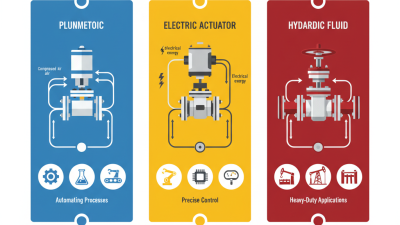
Industrial valve actuators convert a control signal or energy supply into movement that opens, closes, or positions a valve. The required motion depends on the valve design. A gate valve typically needs linear travel, while a ball or butterfly valve usually turns through a quarter-turn. Electric actuators suit precise positioning and sites with reliable power. Pneumatic units can respond quickly where compressed air is available; hydraulic actuators provide high force for demanding duties. Each option has trade-offs.

A 90° quarter-turn sounds simple, but the torque needed can change across the stroke. Seat friction, fluid pressure, temperature, and deposits may all affect operation. For example, a butterfly valve exposed to a large pressure difference may need more torque to start moving than to keep turning. Size the actuator against the valve’s torque data and actual service conditions, not nominal pipe size alone. Allowance matters. Too little capacity can leave a valve stuck; excessive capacity can strain its stem or seating surfaces. Specify the required travel time, duty cycle, and fail position, then check how position feedback will reach the control system. I would also question assumptions about air quality or power reliability. They often look minor on a drawing. In the field, they are not.
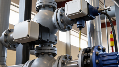
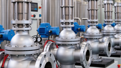
7 Actuator Types Compared by Power Source, Torque, and Application

Valve actuators differ most in their power source, available torque, and response to changing process conditions. Manual handwheels need no external power and suit infrequent operation, but they are slow and depend on operator effort. Electric motor actuators provide controlled positioning and steady torque for larger valves or remote systems. They need a reliable electrical supply. Pneumatic piston actuators use compressed air and deliver fast, repeatable movement; they are common where air is readily available. Pneumatic diaphragm actuators also run on air, but their force and travel depend on diaphragm size and pressure. They often suit control valves that need frequent adjustment.

Hydraulic actuators use pressurized fluid to generate high torque in compact packages, making them useful for large valves or demanding loads. Their power units and fluid lines add maintenance considerations. Electro-hydraulic units combine electrical control with hydraulic force, which can help where air is unavailable but high output is needed. Solenoid actuators switch quickly, though their limited stroke and force generally suit smaller valves. That trade-off matters. Compare the actuator’s output torque with the valve’s breakaway torque, not just its running torque. Temperature, pressure, cycle frequency, and available utilities also affect selection. A sizing estimate can still miss a stiff valve after long idle periods; verify operating conditions and allow suitable margin.

7 Valve Actuator Types Compared by Torque

Typical output-torque ranges in newton-metres (Nm) vary widely with actuator size and design. Use these ranges as a general comparison; always check the actuator and valve specifications for a specific application.

Sizing Actuators for Valve Torque and Thrust Using ISO 5211 Interfaces

Sizing an actuator begins with the valve’s torque or thrust demand, not the mounting flange. ISO 5211 standardizes interfaces for many quarter-turn valves, including flange dimensions and drive arrangements. It helps confirm mechanical fit.

It does not specify the torque an actuator must deliver.

Check the valve maker’s data for breakaway, running, and seating torque at the actual pressure and temperature. A dry valve starting after a long shutdown may need more torque than one cycling regularly.

Small detail, big effect.

Compare the required torque with the actuator’s output across its full travel, including the available supply pressure or spring-return output. Add a suitable margin based on the valve manufacturer’s guidance and operating conditions; excessive oversizing can damage seats or stems.

Then verify the ISO 5211 flange size, bolt pattern, drive insert, and stem engagement. A matching flange can still hide a mismatched insert. For linear valves, confirm the applicable stem interface and required thrust rather than assuming ISO 5211 covers the connection.

Document the assumptions, especially pressure and cycling frequency. That record may need revisiting when the process changes.

Selecting Control Signals: 4–20 mA and IEC 60381-1

For industrial valve actuators, a 4–20 mA command provides a robust way to send position demand across electrically noisy plant areas. IEC 60381-1 describes standard direct-current signal conventions for process control; it does not replace the actuator’s own input specifications. At 4 mA, the command usually represents the lower calibrated position, while 20 mA represents the upper position. This “live zero” can help distinguish a valid minimum command from a broken wire, if the system is configured to detect faults. Check the configured range. Commissioning teams sometimes find scaling mismatches only after a valve moves too far.

Tips: Verify whether the input is active or passive. Match controller and actuator scaling, then test 4 mA, 12 mA, and 20 mA before connecting process control.

During setup, use a calibrated source and compare commanded current with stem or shaft travel. A midpoint check at 12 mA can expose reversed action or unexpected scaling. Confirm how the actuator behaves on signal loss; do not assume it automatically closes. Record the measured endpoints and any deadband. A clear datasheet helps, but field wiring can still surprise you.

Checking Enclosures and Fail-Safe Needs Against IEC 60529 IP Ratings

An actuator’s IP rating describes how its enclosure resists dust and water ingress under specified test conditions. The first digit addresses solid particles; the second addresses water. It does not tell you whether the actuator will survive chemical washdown, salt spray, or prolonged condensation. Those conditions need separate checks.

Match the rating to the actual installation. A unit mounted beside an indoor process line may face occasional splashes, while an outdoor actuator can see windblown rain, dust, and temperature swings. Check cable entries, conduit seals, and the position indicator too. A strong enclosure rating can be undermined by a poorly sealed connection. Small details matter.

Fail-safe behavior is a separate decision. IP protection will not make a valve move when power fails. Confirm whether the actuator needs stored energy, spring return, or another backup method, then verify it can reach the required safe position under process load. That matters. A datasheet may list enclosure and fail-safe features side by side, but they solve different problems. I would also check the required torque with the valve installed, not rely only on a nominal figure. Field conditions are rarely tidy. A little margin is useful, though too much can increase cost and wear. Keep the maintenance plan in view.

7 Best Valve Actuators for Industrial Applications — Checking Enclosures and Fail-Safe Needs Against IEC 60529 IP Ratings

Actuator type Typical valve motion and applications Fail-safe considerations Enclosure ratings to check Selection notes
Pneumatic spring-return quarter-turn Quarter-turn valves such as ball, butterfly, and plug valves; common in process isolation and emergency shutdown duties. A spring can drive the valve to a specified fail-open or fail-closed position when air is lost. Confirm spring torque across the full stroke and operating conditions. IP65 or IP66 options are available for many accessories and switch enclosures; IP67 or IP68 may be offered on specific configurations. Verify the complete assembly. Requires a suitable compressed-air supply. Check air quality, operating pressure, spring range, and accessory enclosure rating.
Pneumatic double-acting quarter-turn Quarter-turn service where powered air is used to drive the actuator in both directions; suitable for frequent cycling and automation. Does not normally provide an inherent fail-safe position. A properly sized air reservoir, accumulator, or separate fail-safe mechanism may be needed. Check the IP rating of limit-switch boxes, solenoid valves, and positioners separately; IP66 is a common option, but ratings vary by configuration. Often provides compact, fast operation. Confirm available air pressure and required torque at minimum supply pressure.
Electric quarter-turn Electric operation of ball, butterfly, and plug valves in utility, water, HVAC, and process systems. A standard electric actuator may stop in place on power loss. Fail-safe operation requires a suitable spring-return design, battery, capacitor, or other stored-energy arrangement. IP66 and IP67 versions are available for some models; IP68 is configuration- and immersion-condition-specific. Check cable entries, covers, and installation instructions. Check supply voltage, duty cycle, motor protection, operating time, and whether manual override is required.
Electric multi-turn Multi-turn operation of gate and globe valves; may also drive linear valves through a suitable thrust arrangement. Fail-safe action is not inherent in a standard unit. Specify stored-energy or external backup provisions if the valve must move after loss of power. IP66 or IP67 options are commonly offered, but the rating depends on the actuator and accessories. Confirm protection for the installed configuration. Check stem thrust or torque, travel, seating requirements, control mode, and the valve’s allowable operating loads.
Electro-hydraulic Quarter-turn or linear duties needing hydraulic force with electrically controlled operation, including remote process applications. Fail-safe behavior may be provided by a spring or hydraulic accumulator. Specify the required final position and verify available stored energy under worst-case conditions. IP66 or higher options may be available for the housing and control components; confirm the rating of the whole assembly and its cable entries. Can provide high force without a plant-wide hydraulic supply. Consider fluid temperature range, maintenance, and leak-control requirements.
Hydraulic actuator High-torque quarter-turn or high-thrust linear operation, including large valves and demanding operating loads. A spring-return design or hydraulic accumulator can provide fail-safe movement. A double-acting unit without stored energy may not move to a defined position on supply failure. IP protection applies to the actuator enclosure and any electrical controls, not to hydraulic connections themselves. Check IP65, IP66, or higher options for the specified assembly. Assess hydraulic pressure, fluid compatibility, piping, power-unit availability, and maintenance access.
Pneumatic linear diaphragm or piston Linear-stem control valves used for throttling or on/off service in process control and utility systems. Many designs use a spring to establish a fail-open or fail-closed position. Confirm the selected action, spring range, and available force at minimum air pressure. Check the IP rating of the positioner, solenoid, and limit switches; IP65 or IP66 options are common, while the actuator’s mechanical housing may be specified differently. Suitable for modulating control when paired with compatible control equipment. Check stem thrust, travel, air supply, and control signal requirements.

Selection note: IEC 60529 IP ratings describe protection against access to hazardous parts, solid objects, and water ingress. IP6X indicates dust-tight protection; IPX5 and IPX6 address water jets, while IPX7 and IPX8 address immersion under specified conditions. An IP rating is configuration-specific: verify the actuator, accessories, cable glands, connectors, mounting orientation, and installation requirements together. IP ratings do not establish corrosion resistance or hazardous-area suitability.