Why Use a Valve Actuator?

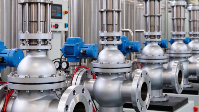
A valve actuator turns a control signal into physical movement, opening, closing, or positioning a valve. That simple action supports safer and more consistent fluid control. In a refinery, a few seconds of delayed response can affect pressure, temperature, and production stability. In a water plant, accurate valve movement can protect pumps and prevent unnecessary discharge.

The need is also tied to industrial energy performance. The International Energy Agency’s Energy Efficiency 2023 report states that industry uses about 37% of global final energy. Better process control can reduce waste, although an actuator alone cannot create efficiency. It must work with correctly sized valves, reliable sensors, suitable controls, and disciplined maintenance. The U.S. Department of Energy’s Better Plants program also emphasizes measurement, system optimization, and continuous improvement across industrial facilities. These principles directly support the practical use of a valve actuator.

Automation brings measurable advantages, but it is not magic. Electric, pneumatic, and hydraulic actuators each fit different operating conditions. A pneumatic model may respond quickly, while an electric actuator can simplify wiring and position feedback. Poor sizing can cause hunting, overheating, air consumption, or premature failure. That uncomfortable detail deserves attention.

Standards such as ISO 5211 help define actuator-to-valve mounting interfaces, while IEC 60534 provides guidance for industrial-process control valves. Engineers should still verify torque, travel, fail-safe requirements, enclosure protection, cycle frequency, and ambient temperature. A dependable valve actuator is therefore more than a motorized accessory. It is a controlled link between process data and physical action. Used thoughtfully, it improves repeatability, safety, and operational visibility. Used casually, it may only automate a mistake.
Why Use a Valve Actuator?

What Is a Valve Actuator?

Why Use a Valve Actuator?

What Is a Valve Actuator?

A valve actuator is a device that moves a valve open, closed, or between positions. It converts energy into controlled mechanical movement. The energy may come from electricity, compressed air, or hydraulic pressure. Some actuators respond to a switch, while others follow signals from an automated control system. In industrial piping, this movement regulates water, steam, gas, or chemical flow. The actuator also supports safer operation when manual access is difficult. Selecting one requires more than matching pipe size. Torque, pressure, temperature, movement speed, and operating frequency all matter. A small error can cause incomplete closure or unnecessary wear.

Tips: Check the valve’s required torque before choosing an actuator. Confirm the power source and available control signal. Add position feedback when operators need reliable status information. For hazardous areas, use equipment approved for the specific environment. Keep manual override access clear. Small details matter.

Maintenance teams often inspect actuator travel, mounting bolts, seals, and electrical connections. Unusual noise may indicate misalignment or excessive load. Slow movement can suggest low air pressure, weak power, or internal resistance. A fail-safe design may move the valve to a safer position after power loss, but the correct position depends on the process. No actuator is perfect. Poor sizing, rushed installation, and irregular testing still create problems. Clear records and periodic functional checks help reveal those weaknesses before they affect production.

How Does a Valve Actuator Operate?

A valve actuator converts a control command into physical valve movement. It may rotate a ball valve or push a gate valve stem. The process starts when a controller sends an electrical, pneumatic, or hydraulic signal. The actuator receives that signal and creates torque or linear force. This movement changes the valve opening and regulates flow, pressure, or temperature.

Inside an electric actuator, a motor turns gears connected to the valve stem. Limit switches stop travel at defined open and closed positions. A position sensor reports actual movement to the control system. Pneumatic models use compressed air to move a diaphragm or piston. Hydraulic models use pressurized fluid when higher force is required. In both cases, the actuator must match the valve’s torque, travel, and operating conditions.

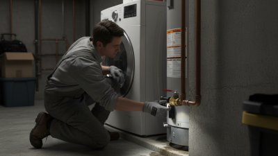
During field checks, technicians often watch the stem, listen for unusual noise, and compare commands with position feedback. A weak power supply can cause incomplete travel. Incorrect calibration can leave a valve slightly open. That small gap matters in a hot process line. Spring-return designs can move the valve to a safer position after air or power loss. Still, “fail-safe” depends on correct engineering. I have seen maintenance plans overlook moisture, temperature, and manual override access. These details deserve attention before installation, not after the first fault.

Which Valve Types Use Actuators?

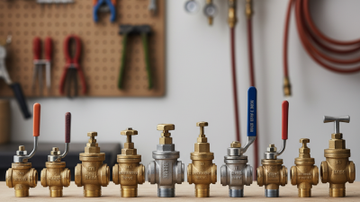
Valve actuators are used when a valve must move reliably, remotely, or on a timed signal. They convert pneumatic, electric, or hydraulic energy into stem or shaft movement. Ball and butterfly valves commonly use quarter-turn actuators. A ball valve rotates a bored sphere, while a butterfly valve turns a disc inside the pipe. Plug valves work similarly, especially where tight shutoff and frequent cycling matter. Gate and globe valves need linear thrust, so their actuators drive a rising stem. Globe valves suit throttling. Gate valves usually isolate. Grand View Research’s 2024 industrial valves report estimates the global market at approximately USD 78 billion in 2023. This scale reflects automation across water, energy, chemical, and manufacturing facilities.

Diaphragm valves also use actuators, particularly where clean operation or corrosive fluids requires careful isolation. Control valves, often globe or segmented-ball designs, pair actuators with positioners for accurate flow adjustment. Check valves usually need no actuator; pressure difference moves their disc or piston. However, actuated check arrangements can support emergency isolation or reverse-flow testing. The International Energy Agency’s World Energy Investment 2024 report estimates global energy investment above USD 3 trillion. More monitored assets create more automated valve duties, although investment does not guarantee good control. Poor sizing can cause slow strokes, noisy throttling, and premature wear. That detail is easy to miss. Selection should match torque, thrust, cycle frequency, fail position, temperature, and maintenance access. A perfect specification can still fail in the field.

Why Use a Valve Actuator? – Which Valve Types Use Actuators?
Valve Type Primary Valve Movement Why an Actuator Is Used Common Actuator Type Typical Control Function Key Operating Considerations
Butterfly Valve Quarter-turn rotation of a disc Provides fast, remote operation and accurate positioning without requiring manual access to the valve. Electric, pneumatic, or hydraulic quarter-turn actuator On/off and modulating Well suited to large pipe sizes because the valve is compact and generally requires less actuator torque than many full-bore designs.
Ball Valve Quarter-turn rotation of a ball Enables rapid shutoff, automated isolation, and remote flow control. Electric or pneumatic quarter-turn actuator On/off and modulating The actuator must provide sufficient breakaway torque to overcome seal friction and pressure-related forces, especially after long periods without movement.
Plug Valve Quarter-turn rotation of a cylindrical or tapered plug Automates isolation in applications where reliable shutoff and straightforward flow-path control are required. Electric, pneumatic, or hydraulic quarter-turn actuator Primarily on/off Operating torque can increase because of plug friction, process deposits, temperature, or differential pressure.
Gate Valve Linear raising or lowering of a gate Allows remote isolation of pipelines and equipment, particularly where manual operation would be slow or physically difficult. Electric or hydraulic linear actuator; motor-operated valve assembly Primarily on/off Gate valves are generally not recommended for routine throttling because partially open operation can cause vibration, erosion, and damage to the gate or seats.
Globe Valve Linear movement of a plug toward or away from a seat Provides controlled positioning for regulating flow, pressure, temperature, or level. Pneumatic diaphragm or piston actuator; electric linear actuator Modulating and on/off The actuator must overcome seating force and process differential pressure; accurate positioning is important for stable control.
Control Valve Usually linear or rotary movement, depending on the valve design Continuously adjusts the flow area in response to a control signal from an automation system. Pneumatic, electric, or hydraulic modulating actuator Continuous modulation Correct sizing, actuator rangeability, position feedback, and fail-safe action are essential for accurate and stable process control.
Check Valve Automatic movement caused by fluid flow and pressure difference Usually does not require an actuator because it operates automatically to prevent reverse flow. Normally none; externally actuated versions are application-specific Automatic operation A separate actuator may be used only when the valve must be forced open, closed, or tested independently of normal flow conditions.
Diaphragm Valve Linear movement of a compressor against a flexible diaphragm Enables remote operation while maintaining separation between the operating mechanism and the process fluid. Pneumatic or electric linear actuator On/off and moderate modulation The diaphragm material, pressure rating, temperature, and chemical compatibility limit the operating range and actuator requirements.
Pinch Valve Compression of a flexible sleeve Automates isolation or flow regulation in systems handling abrasive, corrosive, or solid-containing media. Pneumatic actuator; electric or hydraulic actuator in selected designs On/off and throttling The actuator must generate enough closing force to seal the sleeve against the process pressure and conveyed solids.
Safety Relief Valve Spring- or pilot-controlled lifting of a disc Most designs operate automatically from excessive pressure and therefore do not need a conventional actuator. Normally none; pilot control or auxiliary lifting devices may be fitted Automatic pressure protection Any added actuation system must preserve the valve’s certified pressure-relief function and required fail-safe behavior.

What Are the Main Benefits of Valve Actuation?

Why Use a Valve Actuator?

Valve actuation improves control, consistency, and workplace safety in many fluid systems. Instead of turning a valve by hand, an actuator applies controlled force every time. This matters in treatment plants, process lines, and hard-to-reach installations. Operators can open or close valves from a safer distance. Remote operation also reduces delays during pressure changes or emergency isolation.

The main benefit is repeatable performance. An actuator can position a valve accurately, helping maintain stable flow, pressure, or temperature. It can also support automatic control through sensors and control systems. Properly selected units reduce unnecessary manual effort and help limit operating errors. Electric, pneumatic, and hydraulic options suit different environments and response requirements. However, automation is not a cure for poor valve sizing. I have seen systems perform badly because torque, cycle frequency, or operating temperature was overlooked. Maintenance access can suffer too.

Tips: Check required torque, valve type, cycle speed, power supply, and environmental protection before selection. Include a manual override where practical. Test the complete valve and actuator assembly under realistic conditions, not only on a workbench. Record operating data after installation. Small timing changes can reveal wear before a failure becomes obvious.

How Should the Right Valve Actuator Be Selected?

Why Use a Valve Actuator?

Selecting the right valve actuator begins with the valve’s actual operating conditions, not its appearance. Check the valve type, required torque, pressure, temperature, and cycle frequency. A butterfly valve may need quick quarter-turn movement, while a control valve demands precise, repeatable positioning. Calculate the breakaway torque carefully. Rust, hardened seals, and infrequent operation can increase resistance unexpectedly. Adding a practical safety margin is wise, but excessive oversizing may cause poor control and unnecessary energy use.

Tips: Record the medium, ambient temperature, operating pressure, and failure position. Decide whether the valve should fail open, fail closed, or remain in place. Confirm the actuator’s control signal, enclosure protection, mounting dimensions, and manual override. In wet or dusty areas, inspect the housing rating closely. Small details matter.

I once saw an actuator selected only by nominal valve size. It fitted physically, but the torque demand was underestimated. The result was slow movement and repeated maintenance. That mistake was avoidable. Review the full operating cycle, including startup conditions and emergency movement. Consider pneumatic, electric, or hydraulic operation according to available utilities, response time, maintenance skills, and installation location. A final site check with measured torque is often more reliable than a catalogue estimate. Assumptions should be challenged.