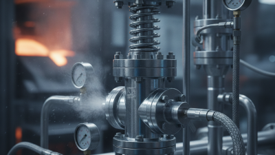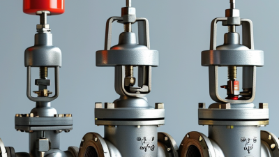
A pressure vessel rarely announces trouble politely. Pressure can rise because of blocked outlets, heating, control failures, or a reaction that accelerates unexpectedly. A safety relief valve provides a mechanical safeguard: it opens when pressure reaches a set point, releases fluid, and helps limit further pressure buildup. Some valves close again as pressure falls; others are designed for different service conditions. The details matter. A valve selected for steam may not suit a corrosive liquid or a rapidly expanding gas.
The U.S. Chemical Safety and Hazard Investigation Board’s T2 Laboratories investigation report describes a 2007 reactor runaway and explosion, in which the installed relief system did not adequately prevent the vessel from rupturing. That incident is not a measure of how often valves fail. It is a useful reminder that a valve cannot compensate for every process hazard. Correct sizing, discharge routing, inspection, and realistic operating assumptions all matter. ASME Boiler and Pressure Vessel Code requirements and API guidance provide important engineering frameworks, but applying them still requires qualified judgment.
What happens inside the valve? In a spring-loaded design, process pressure pushes against a disc while a spring holds it closed. At the set pressure, the disc lifts and flow escapes through the outlet. The valve should then reseat under appropriate conditions. Simple to picture. Not always simple to engineer. Backpressure, contamination, temperature, and incorrect installation can change performance. This guide explains the main valve types, their operating principles, and the practical checks that help engineers choose and maintain a suitable safety relief valve. A small component, with a large responsibility.
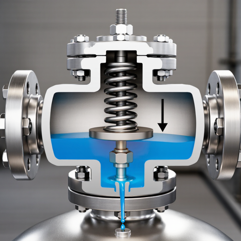
A safety relief valve protects pressure vessels from dangerous overpressure. It remains closed during normal operation. When pressure reaches its set point, a spring-loaded disc lifts from the seat. Fluid escapes through the outlet. Pressure then falls, and the valve reseats. This action may last only seconds, but correct sizing determines whether the vessel survives a blocked outlet, fire exposure, or control failure.
ASME Section VIII provides requirements for pressure-vessel protection, including allowable working pressure, set pressure, valve capacity, and accumulation limits. The design must match the vessel, fluid, temperature, and credible failure scenario. The National Board Incident Report shows that pressure-equipment incidents continue to involve boilers, vessels, and piping across industrial facilities. Its findings repeatedly connect failures with poor maintenance, incorrect settings, and inadequate inspection records. That pattern is easy to dismiss. It should not be.
Tips: Confirm the nameplate set pressure against current engineering records. Check discharge piping for corrosion, blockage, and poor support. During field inspections, look for leakage around the seat. A small leak can become a costly warning. Keep test certificates traceable. ASME Section VIII compliance is not proven by installation alone; inspection, documentation, and competent testing matter. One practical weakness remains common: operators sometimes test the valve but neglect the pressure source. A healthy valve cannot correct an incorrectly calibrated gauge or an unprotected pressure path.
What Is a Safety Relief Valve and How Does It Work?
A safety relief valve protects pressurized equipment when pressure exceeds a safe limit. Its spring, disc, nozzle, and set-pressure mechanism work as one system. A 2024 Grand View Research analysis valued the global industrial valves market above US$75 billion in 2023. This scale reflects valves’ essential role in power, chemical, and process industries.
The spring holds the disc against the nozzle seat during normal operation. Its compression establishes the set pressure. When system pressure reaches that point, force beneath the disc overcomes spring force. The disc lifts, and fluid escapes through the nozzle. A wider nozzle generally supports greater discharge capacity, but sizing must follow operating conditions. API 520 provides calculation methods for pressure-relief device sizing. Small errors matter.
The set-pressure mechanism needs careful adjustment and verification. Technicians compare calibrated test pressure with the stamped setting, then inspect spring corrosion, disc damage, and nozzle deposits. API 527 addresses seat-tightness testing, while API 576 covers inspection practices. Field maintenance often reveals a practical weakness: a clean valve can still perform poorly if the spring loses calibration. Temperature, back pressure, vibration, and installation position can change performance. ASME Boiler and Pressure Vessel Code requirements also influence device selection and certification. Never treat the stamped set pressure as the only answer. Process data must support it.
What Is a Safety Relief Valve and How Does It Work?
A safety relief valve protects pressurized equipment from excessive internal pressure. It remains closed while system pressure stays below its set pressure. A spring, piston, or other mechanism holds the valve disc against its seat. When pressure reaches the calibrated set point, the closing force is overcome. The valve then opens and releases gas, steam, or liquid through a discharge path.
The opening action may be sudden or slightly progressive, depending on the valve design and service conditions. In the field, pressure can fluctuate quickly. Backpressure, temperature, and blocked discharge lines may affect actual performance. This is why technicians verify the set pressure with calibrated test equipment, not visual inspection alone. A small error can matter.
After pressure falls to a safe level, the valve reseats. The disc returns to its seat, restoring the pressure boundary. The reseating pressure is usually lower than the opening pressure. This difference is called blowdown. It helps prevent rapid opening and closing, which can damage the seat or connected piping. However, a valve may not reseat cleanly if dirt, corrosion, vibration, or poor alignment is present. In practice, the first inspection is rarely perfect. Operators should record test results, check the discharge route, and investigate any leakage after reseating.
A safety relief valve opens when system pressure reaches its set point. It releases excess fluid before pressure threatens equipment integrity. Correct sizing starts with reliable API 520 inputs, not a guessed pipe diameter. Engineers define the required relieving rate, set pressure, relieving pressure, temperature, and allowable overpressure. They also confirm the vessel’s maximum allowable working pressure.
Fluid properties control the calculation. Gas and vapor services require molecular weight, compressibility, and heat-capacity data. Liquid services depend heavily on density, viscosity, and pressure drop. Steam needs accurate enthalpy conditions. Two-phase flow is more difficult and deserves careful review. Backpressure matters too. It can reduce capacity or change valve behavior.
Capacity must exceed the credible relief load, with suitable allowance for inlet losses and discharge piping. The selected orifice should pass the required flow without excessive pressure drop. A practical check compares calculated results with process scenarios, including blocked outlets, fire exposure, control-valve failure, and thermal expansion. Small input errors can create large sizing differences. That is easy to underestimate.
Use traceable fluid data and record every assumption. Independent review is valuable, especially when phase behavior is uncertain. Real systems are rarely as clean as design sheets suggest. Recheck the numbers after process changes. Calibration, inspection, and correct installation still determine whether the valve performs when pressure rises.
| Sizing input or check | Why it matters | Gas or vapor service | Liquid service | Steam service | Typical units or record |
|---|---|---|---|---|---|
| Relief scenario and required capacity | Defines the credible overpressure case and the amount the device must discharge. Determine the governing scenario using the applicable design code and process analysis. | Calculate the required mass or volumetric flow for the governing gas or vapor case. | Establish the required liquid flow for the governing case, including the system conditions used in the calculation. | Determine the required steam mass flow for the applicable scenario. | kg/h, lb/h, or actual volumetric flow; document the scenario and calculation basis. |
| Set pressure | The inlet pressure at which the valve is adjusted to begin opening under its specified test conditions. It is selected with reference to the protected equipment’s allowable pressure and governing code requirements. | Use the specified set pressure for the protected system. | Use the specified set pressure for the protected system. | Use the specified set pressure for the protected system. | kPa(g), bar(g), or psi(g) |
| Relieving pressure and overpressure | Relieving pressure is the inlet pressure used for capacity sizing. It is based on set pressure plus the permitted overpressure for the applicable installation and scenario. | Use the applicable code case and pressure basis; distinguish gauge pressure from absolute pressure. | Use the applicable code case and pressure basis; account for the liquid sizing method. | Use the applicable code case and pressure basis for steam capacity calculations. | kPa(a) or bar(a) for absolute-pressure calculations; state the permitted overpressure basis. |
| Backpressure at the outlet | Outlet pressure can affect capacity and valve stability. Consider both superimposed backpressure (present before opening) and built-up backpressure (generated during discharge). | Evaluate the total backpressure and whether the selected valve design and correction factors are suitable. | Evaluate discharge-system pressure losses and their effect on capacity and operation. | Evaluate the discharge piping and outlet pressure for the specified steam conditions. | kPa(g), bar(g), or psi(g); include the basis and expected range. |
| Relieving temperature | Fluid properties at relieving conditions are used in capacity calculations and can affect materials and valve suitability. | Record temperature at the relieving condition for property determination. | Record temperature at the relieving condition; it can affect density and viscosity. | Record the relieving temperature and corresponding steam state. | °C or °F |
| Molecular weight, compressibility, and heat-capacity ratio | These properties are relevant to gas or vapor capacity calculations. Use values appropriate to the relieving composition, pressure, and temperature. | Provide molecular weight, compressibility factor where applicable, and heat-capacity ratio. | Generally not the primary liquid sizing properties; provide fluid composition and properties required by the selected method. | Use the steam-property basis required by the applicable sizing method rather than assuming gas properties. | Molecular weight; dimensionless compressibility factor and heat-capacity ratio |
| Liquid density and viscosity | Liquid capacity calculations depend on fluid properties; viscosity can require a correction or a different sizing approach. | Not normally the primary gas sizing inputs. | Provide density or specific gravity at relieving conditions and viscosity at the relevant temperature. | Not normally the primary steam sizing inputs. | kg/m³, relative density, and mPa·s or cP |
| Fluid phase and service characteristics | Service classification guides the sizing method, valve type, materials, and suitability checks. | Identify composition, phase, and any condensing or two-phase potential. | Identify whether the liquid is clean, viscous, flashing, or potentially two-phase. | Identify steam conditions and any wet-steam or condensate concerns. | Fluid name or composition; phase and service notes |
| Required area and certified capacity | Compare the calculated required area with an available certified valve orifice and verify capacity using the applicable sizing procedure. | Apply the appropriate gas or vapor calculation and relevant correction factors. | Apply the appropriate liquid calculation and relevant correction factors. | Apply the appropriate steam calculation and capacity basis. | Area: mm² or in²; capacity: mass or volumetric flow |
| Inlet and discharge piping | Piping pressure losses and installation details can affect valve performance. Check the complete installation against applicable code and engineering requirements. | Assess inlet losses and discharge-system effects at the required flow. | Assess inlet and outlet losses, including liquid head where relevant. | Assess piping layout, pressure losses, drainage, and discharge routing as applicable. | Piping sizes, lengths, fittings, pressure losses, and installation details |
| Important: This table describes common information used in pressure-relief-device sizing and selection; it is not a completed design calculation. Actual inputs, allowable pressures, overpressure limits, correction factors, and installation checks depend on the applicable code, scenario, fluid properties, and current API 520 procedures. Have the final selection and installation verified by a qualified engineer. | |||||
A safety relief valve protects a pressurized vessel when pressure rises beyond its permitted limit. It opens at a defined set pressure, releases fluid, and reduces the pressure load on the vessel wall. Spring force, process pressure, and valve capacity all affect its response. The valve must also close reliably after the upset condition passes.
ASME Section VIII places a clear limit on single-valve cases. Under applicable non-fire conditions, the vessel pressure generally must not exceed its maximum allowable working pressure by more than 10% while the valve is relieving. This increase is called accumulation. It is not the same as set pressure. For example, a vessel with a 10 bar MAWP may reach 11 bar during the approved relieving event. The selected valve must discharge enough flow to hold pressure within that boundary.
The calculation needs more than a valve nameplate. Engineers check the vessel MAWP, set pressure, relieving temperature, fluid properties, inlet losses, backpressure, and required capacity. A field review should also confirm that the valve is installed upright and that discharge piping stays unobstructed. The 10% rule sounds simple. It is easy to apply it incorrectly.
A common mistake is treating the allowance as extra operating pressure. It is not. Normal operation should remain below the set pressure, with practical margin for control swings and measurement uncertainty. Fire exposure, multiple-valve arrangements, and other service conditions may follow different limits, so the governing ASME case must be identified before sizing. Calculation sheets deserve a second review; small assumptions can change the result.