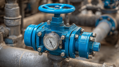
What Is a Relief Valve and How Does It Work?
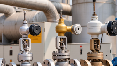
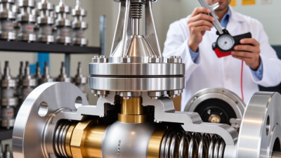
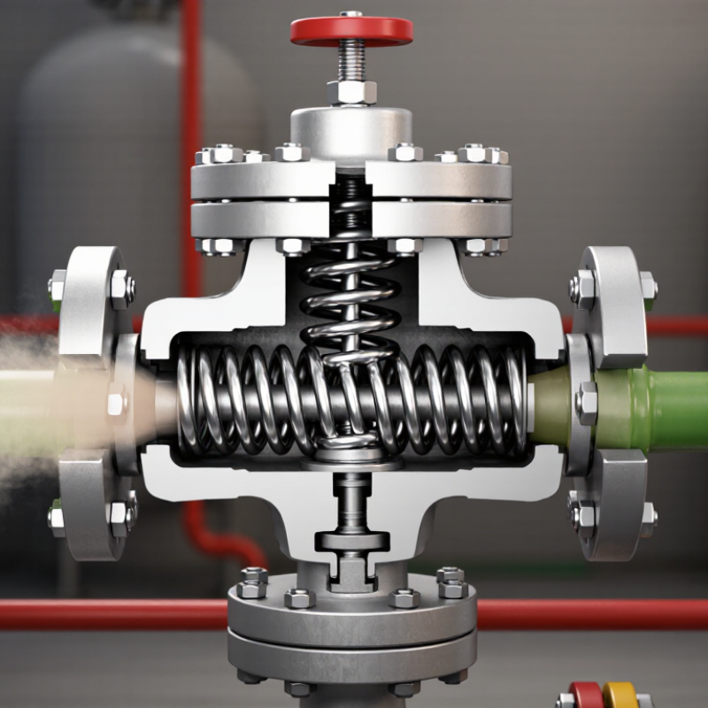
A relief valve is a small but critical device that protects pressurized equipment from dangerous pressure increases. It may appear simple: a spring, a disc, and a discharge outlet inside a metal body. Yet its operation depends on careful engineering, correct installation, and reliable maintenance. When system pressure reaches the valve’s set point, the fluid force overcomes the spring force. The disc lifts from its seat, allowing gas or liquid to escape. Pressure then falls toward a safer level.
This principle appears in boilers, compressors, storage tanks, hydraulic systems, and process pipelines. In practice, a relief valve does more than open and close. Its performance can change with temperature, back pressure, corrosion, blocked outlets, or an incorrectly adjusted spring. A technician may hear a sharp release, see vibration, or find residue around the discharge line. These details can reveal problems that pressure readings alone might miss. Small errors matter.
The terms “relief valve” and “safety valve” are sometimes used interchangeably, although their designs and applications can differ. This article explains the basic mechanism, common valve types, and the conditions that influence operation. It also considers inspection, testing, and practical failure risks. Manufacturer instructions and qualified engineering judgment remain essential. A general explanation cannot replace site-specific calculations. Real systems are rarely tidy. Understanding the fundamentals, however, helps operators recognize unsafe pressure behavior before equipment damage occurs.
Relief Valve Definition and Core Purpose
A relief valve is a mechanical safety device that controls excessive pressure in a system. Its core purpose is to protect vessels, pipes, and connected equipment from dangerous pressure buildup. When pressure reaches the valve’s set point, a spring, pilot mechanism, or similar control moves the valve open. Excess fluid then leaves through a designed discharge route. This action reduces pressure before equipment suffers deformation, leakage, or rupture. The valve closes when pressure returns to a safe range. Small details matter. In practical inspections, technicians check the set pressure, sealing surface, spring condition, and discharge piping. A correct setting is essential, but it is not the whole story.
Relief valves serve different systems, including compressed air, water, steam, and process equipment. Their function is not to regulate pressure continuously like a control valve. They respond during abnormal or high-pressure conditions. The definition sounds neat, but field conditions are rarely neat. Corrosion, dirt, vibration, and poor installation can delay opening or prevent proper resealing. Installation matters too. The discharge path must direct released material safely and remain free from blockage. During maintenance, qualified personnel compare test results with the system design requirements and service conditions. A relief valve can be correctly selected yet still perform poorly after neglect. That uncomfortable point deserves attention. Good protection depends on the valve, the surrounding system, and disciplined inspection practices.
What Is a Relief Valve and How Does It Work?
A relief valve protects pressurized equipment by opening when system pressure reaches its set pressure, releasing excess fluid or gas. The chart shows common pressure benchmarks relative to the valve’s set pressure.
Normal operating pressure is commonly kept below the set point to prevent nuisance lifting. At 100%, the valve is set to open. A 110% level represents a commonly referenced 10% accumulation limit for certain single-device applications under ASME Section VIII; actual requirements depend on the equipment, code, and service conditions.
How a Relief Valve Operates Step by Step
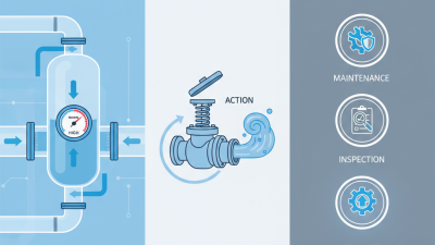
A relief valve protects equipment from excessive pressure. It opens when internal pressure reaches a preset limit. The process begins with a spring pressing a disc against its seat. In other designs, a pilot signal controls the opening force. The setting must match the system’s rated pressure and operating conditions.
As pressure rises, fluid pushes against the disc. When this force exceeds the spring force, the disc lifts. A narrow passage appears. Pressurized fluid then moves through the outlet and into a designated discharge line. Pressure begins to fall. The valve may open sharply, or it may lift gradually. Small details matter.
Once pressure returns to a safe level, the spring drives the disc back toward its seat. The valve reseats when the inlet force becomes lower than the closing force. A technician should check for corrosion, deposits, damaged seals, and blocked discharge paths. Real systems are rarely textbook-perfect. Dirt, heat, vibration, and poor installation can change performance. A test may show unstable opening or slow reseating. That result deserves investigation, not a quick adjustment. Never assume a quiet valve is a healthy valve. Reliable operation depends on correct sizing, clean contact surfaces, and regular pressure testing.
Common Types and Their Typical Applications
A relief valve protects equipment when pressure rises beyond a safe setting. It opens automatically, releases excess fluid, and closes when pressure returns to an acceptable level. A spring-loaded valve is the common choice for steam lines, pressure vessels, and compressed-air systems. Its spring holds the disc against the seat until inlet pressure overcomes the adjusted force.
Pilot-operated relief valves suit large vessels and high-flow process systems. A small pilot mechanism controls the main valve, allowing accurate operation under demanding conditions. Thermal relief valves protect blocked-in liquid sections, such as pump discharge lines or heat exchangers. Even a small temperature increase can expand trapped liquid dramatically.
Vacuum relief valves work differently. They admit air when internal pressure drops too far, protecting tanks from collapse. Selection is not always perfect in practice. Fluid viscosity, back pressure, corrosion, and pulsation can change real performance.
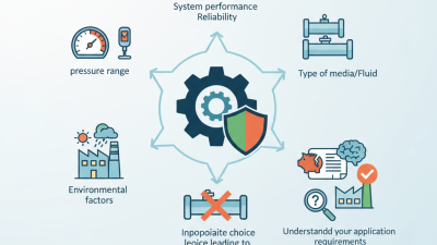
Tips: Confirm the set pressure, temperature range, and discharge capacity before installation. Keep the inlet and outlet paths short, supported, and free from unnecessary restrictions. Check the valve seat for dirt or leakage during maintenance. A pressure gauge near the valve helps reveal abnormal cycling. Do not assume a correctly sized valve will perform well in every position. Pipe layout matters. Manufacturers’ technical data and applicable engineering standards should guide final selection.
Installation, Testing, and Maintenance Considerations
A relief valve protects pressurized equipment when pressure rises above a safe limit.
It opens automatically, releases excess pressure, and closes after conditions stabilize. Correct installation is critical. The valve must match the system’s pressure, temperature, fluid, and connection size. Install it in the approved orientation, usually with a short, unobstructed inlet line. Keep it accessible. Never place debris, paint, or sealing material inside the flow path.
The discharge line should lead to a safe location without creating back pressure beyond the valve’s design limits.
Support the piping separately, because its weight can distort the valve body. A rushed installation can still look neat and perform poorly.
That is an uncomfortable detail.
A qualified technician should verify the set pressure, flow capacity, and applicable engineering requirements before commissioning.
Testing should confirm opening pressure, reseating behavior, and leakage control.
Use calibrated equipment and record every result. In-service testing may reveal corrosion, blocked outlets, or a valve that opens too late. Maintenance intervals depend on service conditions, but visual checks should be routine. Look for vibration, damaged threads, deposits, and signs of discharge. Remove the valve only after isolating and depressurizing the equipment through an approved procedure. Clean parts carefully, replace damaged components, and never alter the spring setting without controlled testing.
Records matter.
They expose repeated failures that memory often misses.